Parabolic Microphones
Accuracy Requirements for Parabolic Reflectors
Introduction
This article will explain the requirements of a parabolic reflector for use with a microphone, and answer the question, “How accurate does a parabolic dish need to be, and how good should it work?”. The information will be confined to only address the dish accuracy; numerous other issues can also affect parabolic microphone performance even at lower frequencies – see our other Articles for more. The concept of a Parabola will be explained first, and how it functions with a microphone. Then gain, the main reason a parabolic dish is used, will be discussed, and the accuracy requirements to realize that gain. You will also learn a simple method to check the accuracy of any dish. We hope this information will improve your understanding of the subject, and help dispel the misconceptions, deliberate misleading information, and resulting confusion about parabolic microphone dishes and their use. First you may want to read our other articles for background information about the basic concepts of dBs and sound which will not be explained fully here.
What is a Parabola
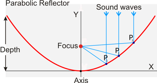
A Parabola is a type of mathematical function know as a Quadratic Function. Don't get worried, it is a very simple function, see Figure 1. Equation 1) Y = aX^2+b, is the Parabolic function, it is used to calculate the Y value, for any X value which is the radius. When the Parabola is spun around on it's axis, creating a bowl-like shape, it is then called a Paraboloid. For a simple parabolic reflector example, b always = 0, a= the shape constant, say .06. Now, Y is the vertical point on the curve that can be calculated for each X radius up to 10, for say our example 20-inch diameter reflector. Figure 1 is a graph of the resulting shape. Notice that the example dish is 6.0 inches deep, and the focal point is 4.17 inches. A different shape factor will give you a different depth and focal point. Later we will show you how to check any dish for compliance with a Parabola, using Equation 1), simple rulers, and a hand calculator.
Figure 1
Paraboloids Used with Microphones and Accuracy Required
A Paraboloid shape has TWO very important properties that make it suitable for use with a microphone that no other shapes have: Referring to Figure 1 again, you will notice there is a virtual focal point (F), which is easily calculated, F = 1/4a. This focal point has: 1) Equal path lengths for incoming sound waves from the distance, from anywhere on the dish. 2) The angle at each point on the dish allows sound waves to reflect exactly to the focal point. These two intrinsic properties allow sound collected by the parabolic dish to concentrate at the focal point, where you then locate your microphone, see Figure 1. This principle is exactly analogous to an astronomical reflector telescope, which is also a perfect parabola. This is only true for a parabola. A spherical section or any other shape will not yield a proper focus. With a telescope, the image would become blurred, and with sound the gain will suffer losses as frequency increases.
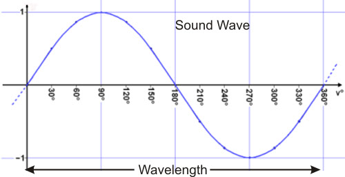
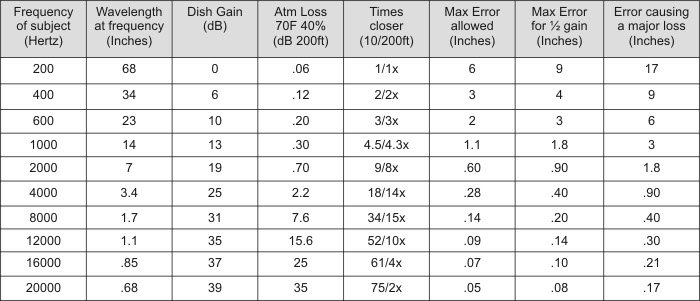
Now, let's look at what sound waves actually are: Sound waves are pressure fluctuations in the air, and they travel at the speed of sound, which is about 1130 Feet per Second. This motion causes a very important principle in understanding how the sound waves will behave when encountering the reflector. The sound waves develop an actual length called their wavelength, Wavelength in inches = 13560/Frequency, see Table 1. Their wavelength determines their behavior and gain in a parabolic microphone. Within each wavelength, the sound pressure will be increasing during half the wavelength, and decreasing during the other half, see Figure 2, forming a sine wave. Since the entire dish surface is collecting sound energy, many separate wave fronts are being combined at the focus. If two sound waves arrive at the same exact time, or in phase, they add together and become louder. If two sound waves arrive 1/2 wavelength apart, or 180 degrees out of phase, they subtract and cancel, resulting in no sound level. Remember that the paraboloid has equal path lengths for each point on the surface so all wave fronts arrive in perfect phase, when pointed accurately. Intermediate arrival distances will be between the two extremes, but for reasonable addition, like we want, all the arrival distances will have to be within about 1/6 wavelength. If the paraboloid dish is collecting the sound from a distant point, each point on the dish will then have to be accurate to 1/12 wavelength, to allow all the sound waves to add together in phase. Any parts of the dish, or the microphone location from exact focal point, exceeding 1/12 wavelength, will cause looses at that frequency and above. Note that 1/12 is half of the 1/6 wavelength requirement, since an outward error in the reflecting surface delays the sound wave in getting to the surface, and then again in getting to the microphone, doubling the phase error. When errors approach 1/4 wavelength, those parts of the dish will cancel the gain from other parts of dish, leading to a rapid gain loss at that frequency. The last column in Table 1) is the error in inches where this rapid gain loss occurs. So, if you only need your dish for frequencies up to around 1KHz, where not much gain is available yet, such as for male human voice, an accuracy of one inch is acceptable, and a non-paraboloid shape or Wok may be okay. For most anything else, like birds or wildlife research, with harmonic frequencies from 10-20KHZ, you will need to hold an accuracy of 1/16 of an inch for the reflector and mic focus! See Table 1, column 6. Humans typically hear up to 10-20KHz, so for a life-like recording, you will need to capture these higher frequencies, especially when atmospheric attenuation is considered.
Figure 2
How Much Gain Should a Good Parabolic Mic Have
A Parabolic microphone gain is highly predictable, and when properly made, closely approaches the theoretical values given by the Gain Equation below: Where Dish Gain in dB = G, Diameter in inches = D, Wavelength in inches =W, and E is the efficiency from 0 to 1. The Gain equation is: G = 20Log(3.25DE/W). For a hypothetically perfectly made system, E will equal 1. Table 1 tabulates the Frequency, Wavelength, Dish Gain, how many times closer a subject would seem without/with atmospheric attenuation, the maximum errors allowed for realization of this perfect 20 inch dish, and the frequencies losses as errors increase. Figure 3 is a plot of the Gain response for this ideal dish, and plots of dishes with specific amounts of error. Inspecting Table 1, note how close a high frequency subject can appear, and how atmospheric attenuation reduces this at the higher frequencies. Note, that gain in a parabolic mic is proportional to frequency, and only excels when used above a few hundred Hertz. It should be pointed out that this is what should be expected from an ideal parabolic microphone, but many are falling far short of this due to reflector errors and other constructional issues even at the lower frequencies! The Max error for the 1/2 gain column in Table 1 is how much error in inches, you can tolerate at each frequency before your dish gain is 1/2 or -6dB. A 6dB loss or 1/2 the gain is what a 10 inch diameter dish would have, and you will then need to approach your subject twice as close. Figure 3) is an excellent way to visualize the dramatic effects on frequency caused by what seems like small errors in the reflector or focus. Unfortunately, many dish users have come to accept poor performance as normal, but it is certainly not normal. Wildtronics, with their Patent pending enhancements, and perfect paraboloid, closely approach the expectations of the ideal dish in Table 1 and Figure 3.
Figure 3
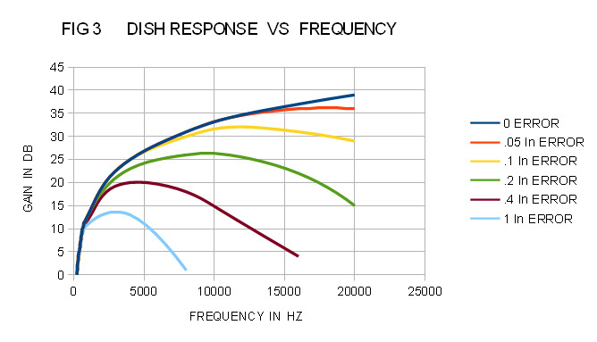
You will need all the high frequency gain you can get, both to increase your subjects overall sound level as much as possible, and to overcome atmospheric attenuation over the extended distances parabolic microphones allow. In Table 1), you will also see a column for Atmospheric attenuation, this is the additional loss over a 200 foot distance, for 70F and 40% humidity. For much more humid conditions like 90%, half the value, for very dry conditions like 20%, double the value. You can see how much gain is lost at higher frequencies, and why you would need as much gain as possible to retain proper harmonic content. See our other Articles for more information, including how to normalize your frequency response at any distance for an accurate, true to life, recording. Normalization allows you to have the remarkable gain that parabolic mics offer, compensate for atmospheric loss, and have a flat frequency response all at the same time!
Table 1
How to Check Any Dish for Accuracy
You can also use the Parabolic Equation 1) above to check any dish for accuracy. Here is how: Measure the maximum radius, Xmax, and depth, Ymax. Now calculate the shape factor with Equation 2), a = Ymax/Xmax^2, and record it. The Parabolic Equation 1) above, with the shape factor from Equation 2) will then give you the proper Y value for each radius of the dish, allowing you to compare the dish to the actual required parabolic shape. Before you begin, measure and record the inner rim diameter at several points, and record the maximum difference as ovality, a paraboloid has to be round not oval, so this error is just as important as an error in the parabolic shape.
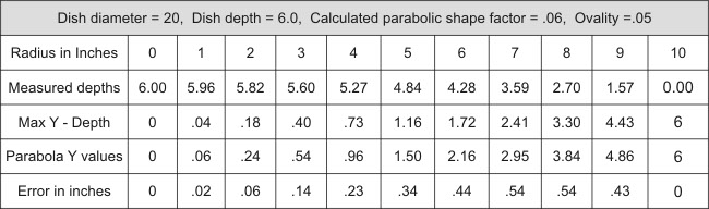
Start by organizing your information, label a piece of paper with a column for each inch of radius starting with zero, see Table 2). The first row will be your radius. Place the edge of a stiff rule or yardstick across the exact center from rim to rim, and clamp it with spring clips. Place another ruler at exactly 90 degree angles (a sliding combination square works perfect), and measure and record the exact Y depth to the inside surface, for each inch of radius from the center out, along the stiff ruler, and record in row 2. Now, subtract each value in row 2 from the total depth Ymax, and record in row 3; these are the Y values of your dish. Now, using Equation 1) with b=0, and the shape factor from Equation 2); calculate Y for each inch (X value) measured, and record in row 4. Subtract row 4 from row 3, and record the result in row 5. Row 5 values are the differences or errors from a true Parabola of your dish. You can do this in about an hour to check a suspect dish, evaluate various shapes for use as a paraboloid, or even to check one of our dishes. You should not find more than a 1mm error with a Wildtronics dish.
Take the larger, of the maximum errors from row 5 or the ovality difference first measured, and look at Table 1 or Figure 3 to gauge how well your dish will perform. The preferred accuracy in inches for near theoretical gain at each frequency is in the first Error column, the second Error column is where gain will drop in half (6dB), and the third Error column is where gain almost disappears rendering the dish useless. You will not find many suitable shapes in everyday bowls or whatever to make a dish with reasonable performance, that also have a usable focal distance.
Table 2) is an interesting example of the above method put to use, the dish measured is 20 inch in diameter, 6.0 inches deep, and is a known spherical section (fairly common) which looks like a paraboloid to the eye, but is not. The ovality measured was .05, good compared to some dishes. You can use the Table 2) example for guidance to make sure you are doing everything right. Note, in row 5 the maximum errors came to .54 inches from an exact Parabola that is also 20 inches in diameter, 6 inches deep, with a shape factor of .06. Referring to Table 1) or Figure 3), with the .54 inch error, the system would be good to about 2KHz, gain would drop in half by 3KHz, and would become unusable by 6KHz. The errors are about 10 times of what is acceptable. Some expensive commercially made “parabolic mics” actually use spherical sections for their dish! Try asking them what their frequency response and gain is, and get a straight answer before spending a lot of time and money using something inadequate.
Table 2
Summary
Through the unique inherent mathematical properties of the Parabolic Function, we have seen how sound can be greatly amplified so subjects can seem much closer than they actually are. However, keeping the parabolic microphone system usable over the full range of human hearing, requires considerable accuracy (.06 inches) for both the reflector and microphone location. Although any dish may offer some improvement over an unaided microphone at low frequencies, full performance is only possible with a dish that closely conforms to a true parabola and has an accurate focus. With such a properly performing parabolic microphone, frequency response is known (6dB/octave), gain is high, sufficient harmonic energy is captured, and this makes good recordings and frequency normalization possible. Good gain, low noise, a few other critical construction issues, and frequency normalization are the key to creating perfect long-range, life-like recordings with a parabolic microphone. With a properly performing parabolic microphone, you can generally expect at least 10 times the range of a standard cardioid microphone! All the Wildtronics models, with booster plates, were designed to realize the performance standard of the ideal parabolic reflector explained above. Combined with it's low-noise microphones and other features, Wildtronics Parabolic Microphones are capable of meeting the most demanding expectations. Just because parabolic microphone manufacturer's use the term Parabolic, does not mean it is actually a true parabolic reflector, and the results are likely to be inferior to the above standards.